Building a PID-Controlled Robotic Car for Straight-Line Path Tracking
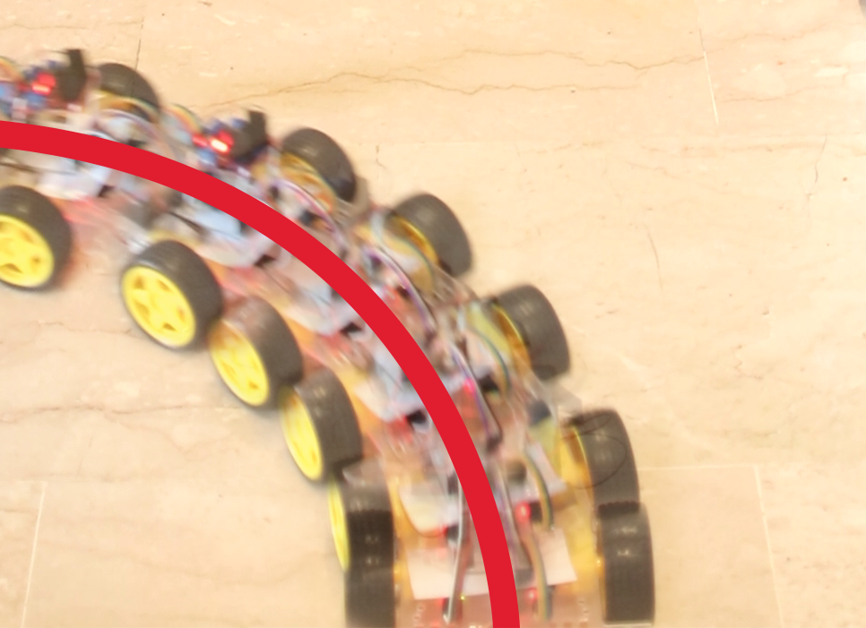
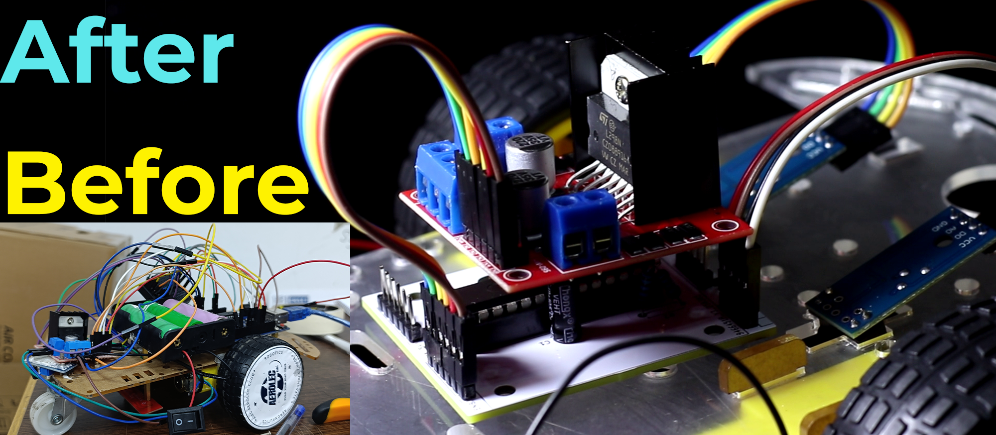
Final Result: Before / After PID Control:
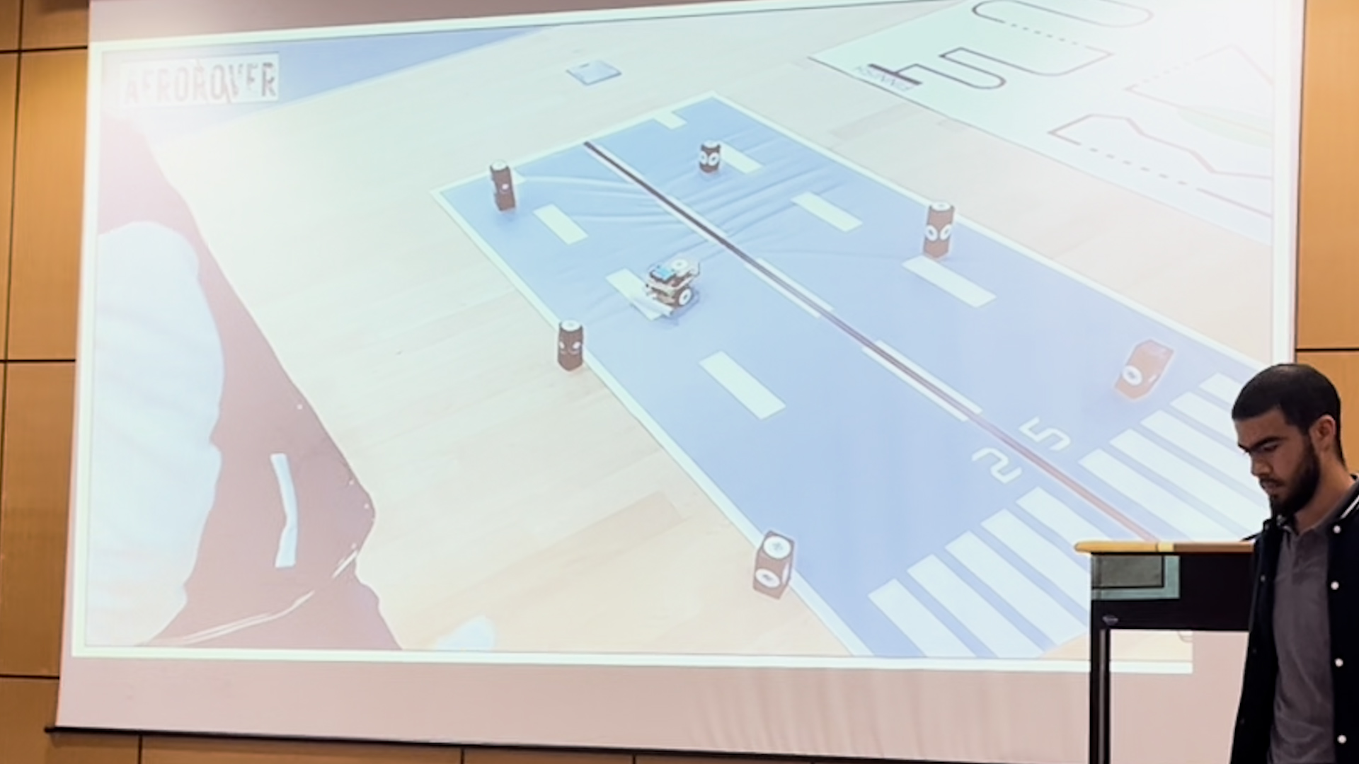
Let's enjoy the final result before delving into the depths of technical details.
Detailed Video Coming Soon...
\
Introduction
After securing 🏆 1st place in the first edition of AeroRover's National Robotics Competition, I decided to continue on the idea of the robotic car we made during the competition. It was too cool to leave behind. There was a particular problem that intrigued me.
What Problem Are You Talking About?
The challenge is that DC motors that are commonly used for robotics are imprecise, hard to control and exhibit inconsistencies simply due to manufacturing differences. (i.e applying the same voltage on each motor does not (and almost never) guarantee producing the same rotational speed).
That being said, and knowing that a common robotics car uses a motor for each wheel (differential drive), any slight speed difference between the two motors will lead the car to veer off-trajectory.
Here come Control Systems.
Proposed Solution
If I succeed to calculate the deviation off trajectory based on the motors' total angle of rotation (spoiler: I did), then it will no longer be my problem, and will be the magic of PID's problem.
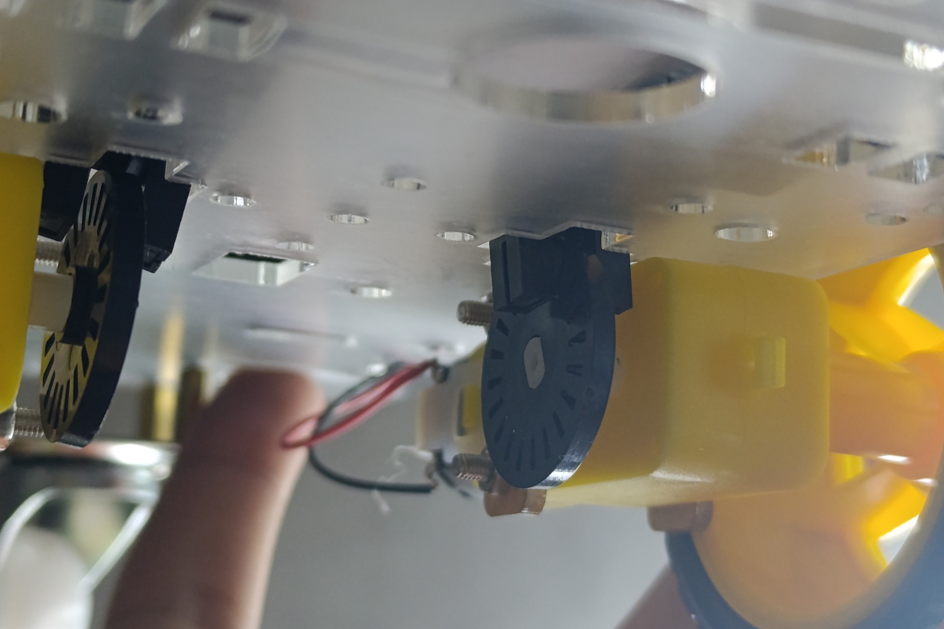
The total angle of rotation is given by photointerrupter-based encoders.
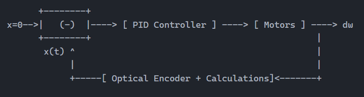
So here's basically the feedback loop:
Step 1: PCB Design
Being the sane person that I am, I hated all the wiring that came with the plenty of components required for the competition, which naturally creates a havoc of problems (faulty wires, wires disconnecting every now and then, without you noticing...), especially when time was not our friend that week.
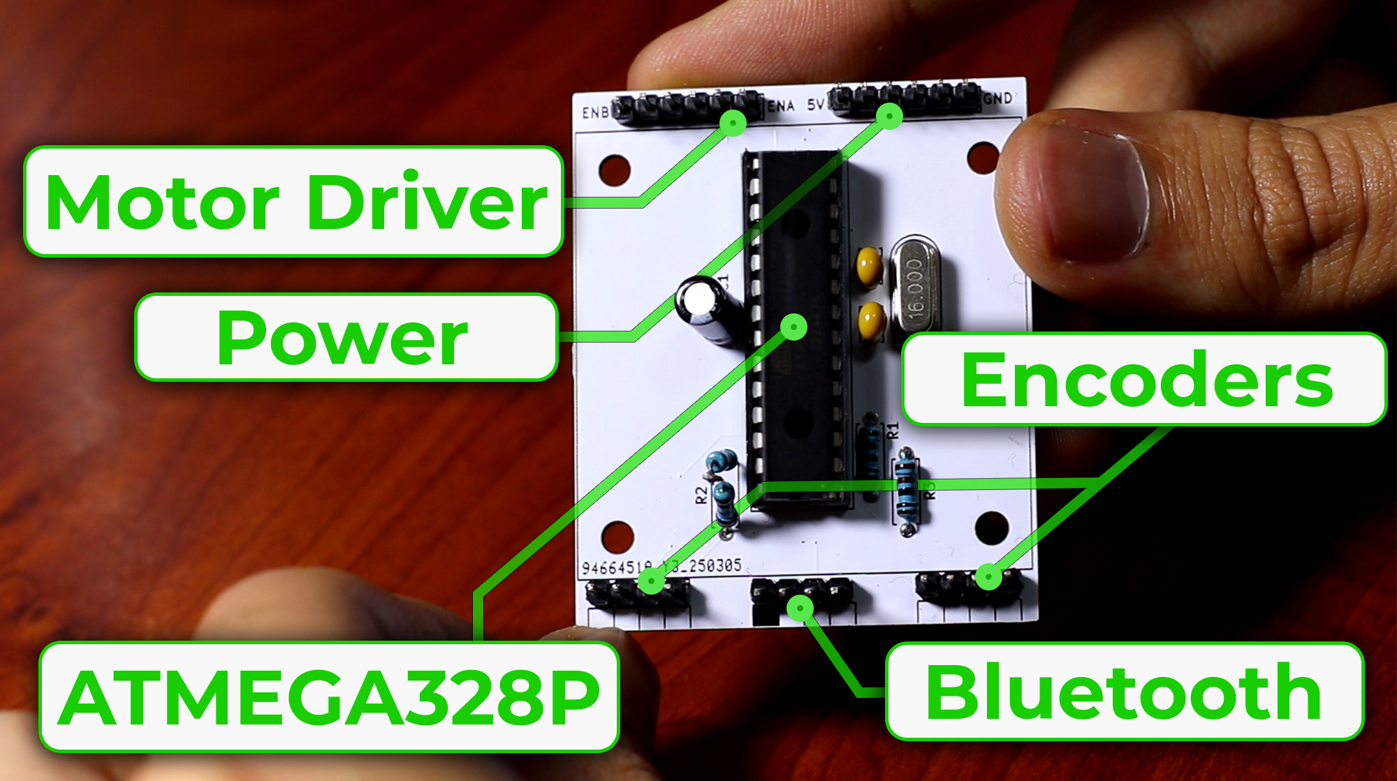
So immediately after deciding to start this project, the first thing I did was design a custom PCB to host all the components and minimize the space taken by the Arduino board and the wires.
(For this project, I went for a simple THT layout instead of SMD, for the sake of components availability.)
.png)
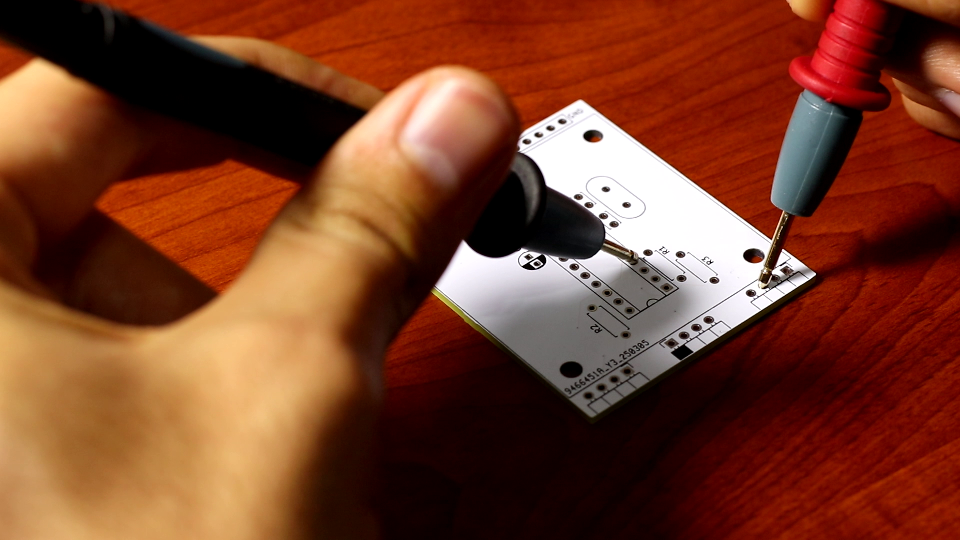
I swiftly tested the connections using my multimeter.
Soldering was fun. Soldering is always fun, as long as you do not overheat your capacitors (🗿).
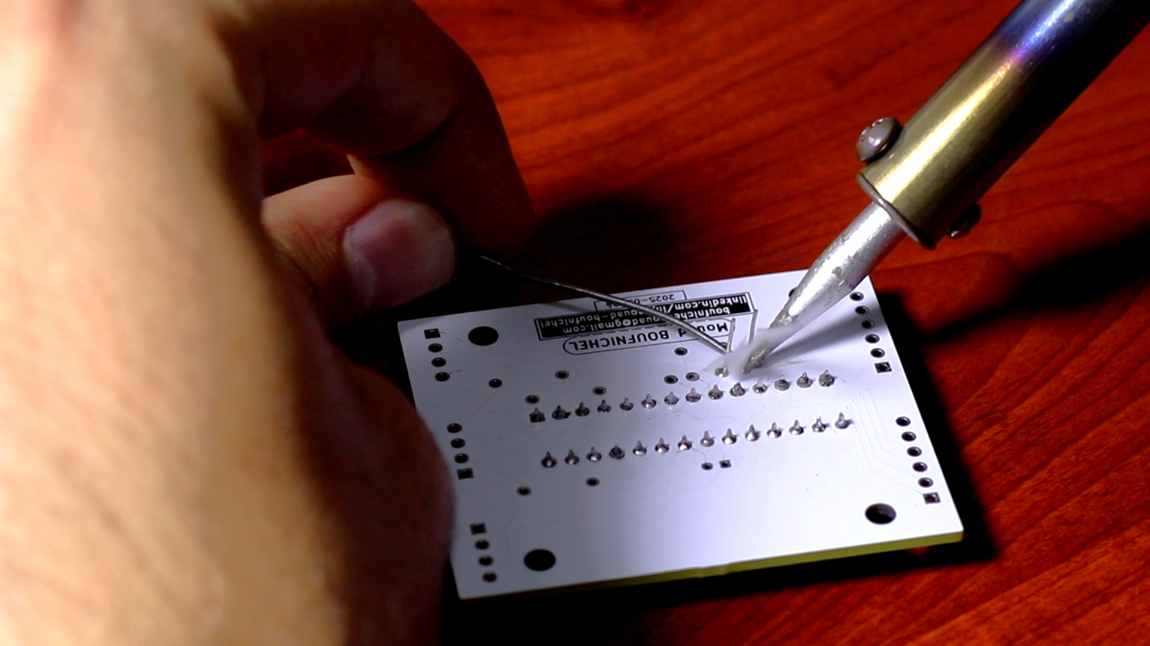
Final Product: Clean.
Step 2: Mathematical Error Modeling & PID Algorithm
Maths
I did some mathematical shenanigans to find out the error as a function of the wheels' total angle of rotation (given by the encoders).
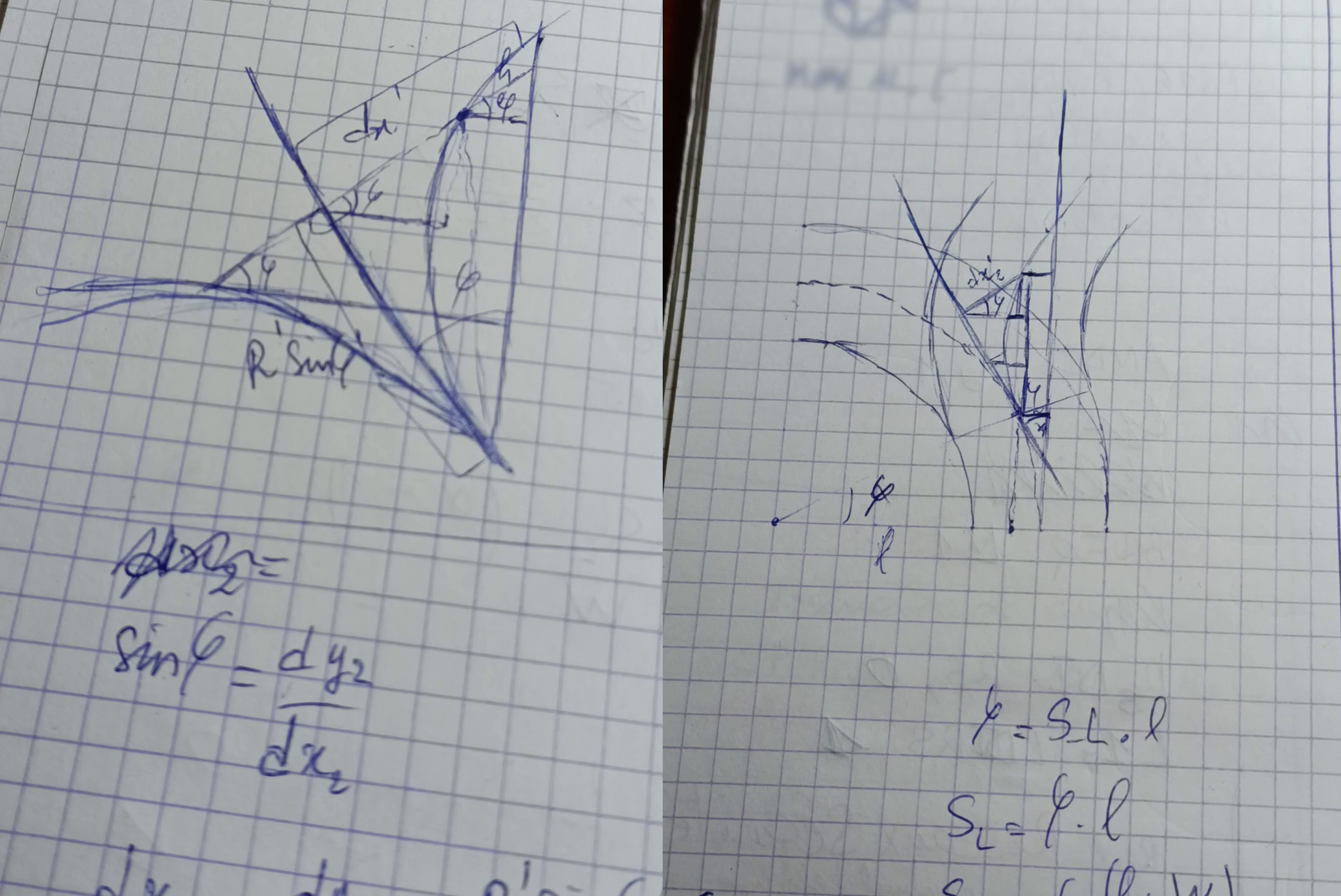
After pages filled with blue ink (which reminded me of the glory of preparatory classes' days), I finally found out that I can divide the calculations into two parts: position myself in a relative basis
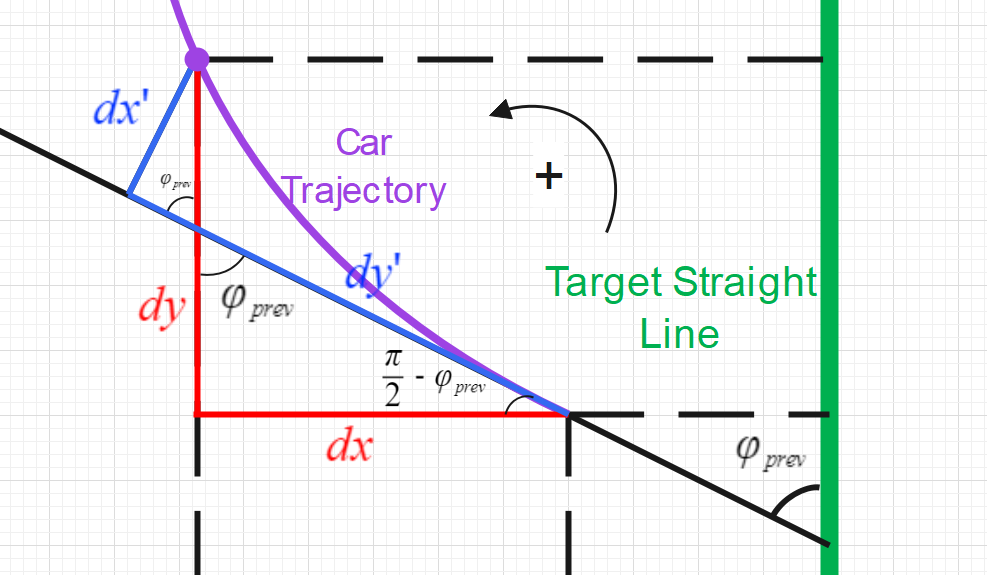
That's basically the idea, but I will not delve into the geometrical details (they do give headaches but they're pretty intuitive, just playing with some cosines and sines):
In the relative basis:
(
Projected on the global basis:
Then we add the small changes
And just like that, we have the car's coordinates
In our control loop, simply:
PID Code Implementation
I implemented all the above into the ATMEGA's code.
The goal is simple: if one motor dares to run faster than the other, the system should politely (but firmly) tell it to calm down. To do so, we read the total rotation angle from both encoders, calculate the error, and let the PID algorithm adjust each motor's PWM signal accordingly.
Here is the PID loop:
  ...

  double dS_L = ((theta_L - theta_L_prev)*pi/180) * wheel_radius;
  double dS_R = ((theta_R - theta_R_prev)*pi/180) * wheel_radius;

  double dphi = (double) (dS_R - dS_L) / W;

  double dxp;
  double dyp;

  if(dphi == 0.0){
    dxp = 0.0;
    dyp = (double) (dS_R + dS_L)/2; // which is == dS_L == dS_R
  }else{
    dxp = (double) - (dS_R + dS_L)/(2*dphi) * (1 - cos(dphi));
    dyp = (double) (dS_R + dS_L)/(2*dphi) * sin(dphi);
  }

  double dx = cos(phi_prev) * dxp - sin(phi_prev) * dyp;
  double dy = sin(phi_prev) * dxp + cos(phi_prev) * dyp;

  x += dx;
  y += dy;

  error = x;

  P = error;
  I = I + error;
  D = error - error_prev;


  // Transitionning n-1 --> n;
  theta_L_prev = theta_L;
  theta_R_prev = theta_R;
  phi_prev = phi_prev + dphi;
  error_prev = error;

  motorSpeedChange = (int) (Kp*P + Ki*I + Kd*D);

  motorSpeedA = basespeed + motorSpeedChange;  // RIGHT WHEEL
  motorSpeedB = basespeed - motorSpeedChange;  // LEFT WHEEL

  ...
PID Tuning
First Phase
This phase actually represents a phase where I was shooting in the dark without knowing. Because this was before establishing the correct mathematical error model I talked about above. I had a close but incorrect model.
Unfortunately, it wasted a lot of my time. Because It DID NOT look like the model was incorrect. Not until I took the car and manually moved it, and the real trajectory and the plotted one (see HMI app below) did not match.
That was the moment where I revisited my calculations and changed my approach.
Second Phase
With a correct error model now, I began experimenting with random gains.
After some trials, I thought "if I give an absurdly high value to the derivative gain
With a high
And in practice, that was surprisingly accurate. Only small
The final gains I was satisfied with were:
Nerdy Details
Problems that wasted my time (actually joking. The various moments where you struggle with unexplained problems are exactly the moments where you actually learn something new):
- Truth #1: Photointerrupter-based encoders are NOT continuous. The real curve of the recorded angle is a staircase.
- Truth #2: The clock frequency of the ATMEGA328P on my board is 16MHz, which is way superior to the frequency of the encoders change.
- (20-slot encoder wheel, car velocity would not surpass
- (20-slot encoder wheel, car velocity would not surpass
).
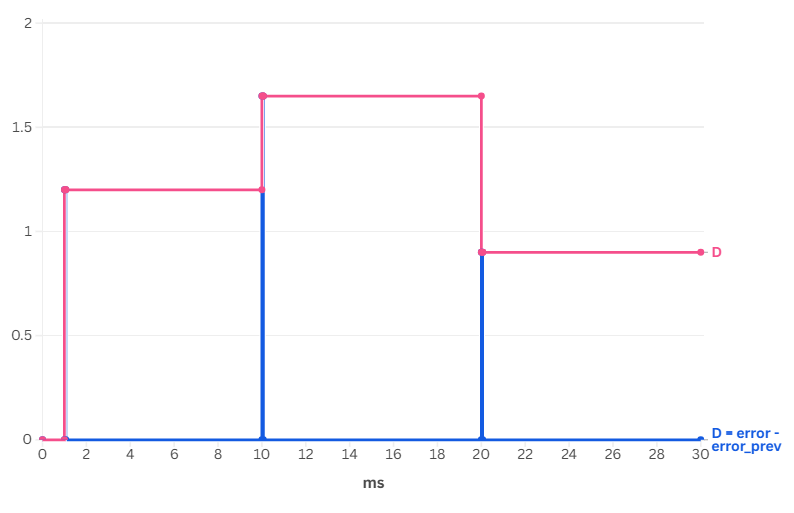
So the ATMEGA's fast loop quickly crushes the derivative term
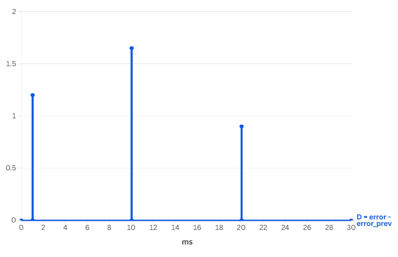
To correct that, I transformed those spikes into stable staircases in the code, by not updating
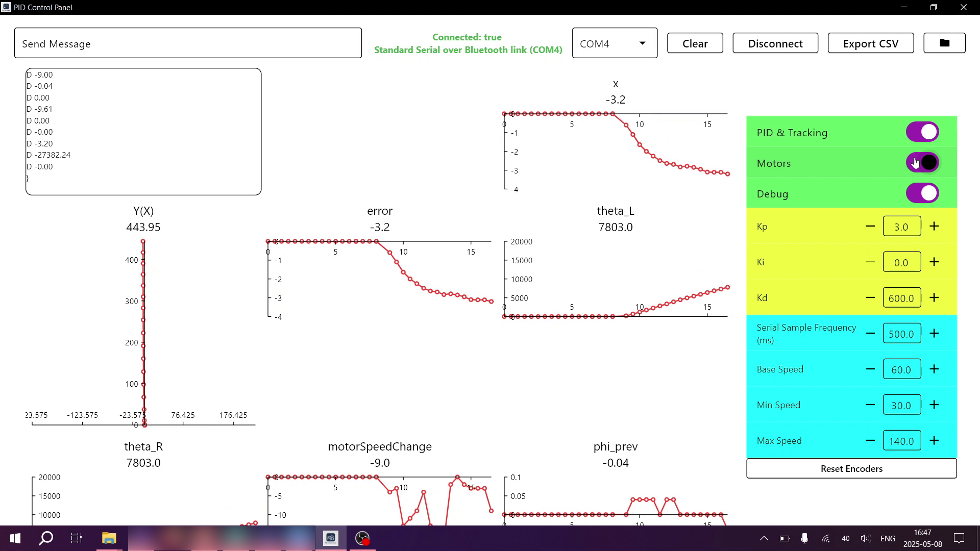
Step 3: Flutter HMI App / Control Panel (because why not?)
What's the fun of building a robot car if you can’t control it from your PC and feel like a real engineer?
I built an HMI (Human-Machine Interface) app using Flutter. The app connects to the car via Bluetooth, and lets me do things like adjust PID constants, toggle PID, motors and debugging, and export every plotted variable to an .csv file for later analysis.
It’s sleek, minimal, and does exactly what it needs to. Also, it gave me a reason to play around with Flutter again.
The Journey of Variables from ATMEGA's Memory to Being Plotted on The Flutter App's Graphs
How am I able to visualize the live value of a variable, e.g $theta\_L$ (i.e the left wheel's total angle of rotation in radians)?
- We have a variable
Xwe want to transmit - We convert
Xto aStringregardless of it's real type (int, double...). - We send
Xthrough HC-06's (bluetooth module) TX serial output.- The conversion to string earlier is due to the fact that serial inputs and outputs by default send
charbychar, i.e, byte by byte. So the easiest route is to send data as a string. So the integer 6 should be converted to the character '6' before being sent. - I send them in a format that I understand and that it is easy to re-decrypt (in Flutter code) once on my PC's side:
which translates to:{@158@ D 0.18 D NaN D 918 D 0.00012 ... ... }
The order of the variables is important and predefined.{@(current transmit cycle)@ D (value of variable 1) D (value of variable 2) D (value of variable 3) D (value of variable 4) ... ... }
- The conversion to string earlier is due to the fact that serial inputs and outputs by default send
- The Flutter app on my PC, which is already paired with HC-06, reads this chunk/stream of bytes (characters)
- Once this chunk arrives at my Flutter app, I extract/isolate the variables with some string manipulation and reconversion to the original data types (integer, double...).
- Now everything is set! I now have them as variables on my Flutter app and can now plot them for some aesthetically pleasing data visualization.
Recap:
C variables on the ATMEGA --> Formatting --> Chunk of strings --> HC-06 --> PC's bluetooth --> Received chunk of strings --> Parsing --> Variables on the Flutter HMI that can be plotted
🐰 "That's all, Folks!"
What's Next?
At this point, the project is functional and very fun to demo. But I’m not done yet.
✅ I plan to upgrade the "straight line" to whatever trajectory you can draw with your hand. Then I can really call the car a self-driving car.
✅ I’d like to upgrade the chassis (probably going for 3D printing) — right now it’s... modest. Let’s call it modest.
✅ And of course, I need to publish the detailed walkthrough video.
Final Thoughts
This project started as a continuation of a competition win, but it quickly evolved into something I genuinely enjoyed building, debugging, and iterating on. From designing the PCB to soldering the components, from modeling the error mathematically to building an interactive remote control panel — it brought together many of the things I love doing.
I feel like this is real engineering.
Also, bonus: no more tangled wires 💀.
If you read this far, feel free to check out my other projects or shoot me a message if you want more technical details or if you're working on something similar.
See you in the next build!